Solved circuit diagram was not drawn as as a designer for In this guide, we will explore different types of motor control circuits, including their wiring diagrams and key advantages and disadvantages. Types of Motor Control Circuits. Direct Online (DOL) Starter; ü Simple and cost-effective. ü High starting current, leading to voltage drops. ü Suitable for smaller motors
Motor Structure + Design. Motors have a standard set of parameters that determine their performance, we design to these parameters, but they also have many considerations associated with them. Here are some. General selection of poles and slots in motor design. Power + Transmission Design MIT 2.75 - look @ the middle section about motors A contactor is a large relay, usually used to switch current to an electric motor or another high-power load.; Large electric motors can be protected from overcurrent damage through the use of overload heaters and overload contacts.If the series-connected heaters get too hot from excessive current, the normally-closed overload contact will open, de-energizing the contactor sending power to the

PDF EMC design guides for motor control applications Circuit Diagram
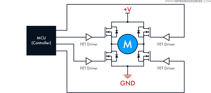
EMC design guides for motor control applications Alessio Corsaro, Carmelo Parisi and Craig Rotay Introduction . In recent years, continuous demand for efficient, compact and low cost applications in the motor control industry has led to a boom in inverter-based solutions driven by MCUs. These applications involve high

This example covers a hypothetical and uses the principles of high-power design to improve a high-power motor driver application. Note, this example serves to show that how the process is utilized and rest of the application note explains the theory that eventually results in the process used. Consider the following example:
A Comprehensive Guide to Motor Control Circuits: Types, Wiring, and ... Circuit Diagram
after researching commercially available motor driver boards and finding that most were either kinda wimpy(see included comparison photo) or rather expensive i decided to design a simple Arduino based solution Design Brief . 24v minimum. bi-directional motor control. PWM control. scalable high current capable( 100AMP) minimal components. 5v
The goal of this project is to design a high-power motor driver that can: 1. Drive a DC motor with a high current rating (up to 40A). 2. Allow control over motor speed and direction. 3. Be used in various high-power applications such as robotics, electric vehicles, or heavy machinery. 4. A switching regulator has higher efficiency and less power loss, and PWM is widely used in speed controller design for DC motors. Motor Power. Motor power relies on the current supplied by the power source. Thus, a low-power BDC motor needs a low current controller and vice versa. A high current DC motor controller typically uses a switching
