Make a Transistor Voltage Regulator Simple Electronic Project Circuit Diagram Aim To design and set up a transistor series voltage regulator using BJT and Zener Diode. Load current vs output voltage Input voltage vs output voltage for a constant load current Apparatus Required: Breadboard,PCB Circuit Diagram:

Voltage regulators are an essential part of any electronic circuit, ensuring a stable output voltage despite changes in input voltage or load conditions. One of the simplest and most effective designs is the series voltage regulator using a Zener diode and a transistor. In this blog post, we will walk through the design of a basic series regulator, its calculations, and its advantages over Learn how voltage regulators work and how to build three different voltage regulator circuits. Learn how to design a voltage regulator circuit using zener diode, transistor and resistors #unregulated power supplyzener diode regulatorzener and transitor

Designing Voltage Regulators with Zener Transistors: The Definitive Guide Circuit Diagram
All linear power supply circuits which are designed to produce a stabilized, constant voltage and current output fundamentally incorporate transistor and zener diode stages for getting the required regulated outputs. These circuit projects using discrete parts can be in the form of of permanently fixed or constant voltage, or stabilized adjustable output voltage. What is a Voltage Regulator A voltage regulator with a transistor usually consists of a bipolar junction transistor (bjt) with high current handling capability in an emitter follower configuration, driven by zener diode and resistor potential divider (PD) network. Transistor - Zener Voltage regulator This circuit delivers an output voltage established by the voltage of the zener diode - 0.7 volts. The 0.7 volts is the average voltage drop between the base and the emitter of a transistor. (Vbe). So, Vout = Vz - Vbe = Vz - 0.7 V. When the unregulated voltage goes up, the zener diode current will also go up. The voltage across the zener diode has

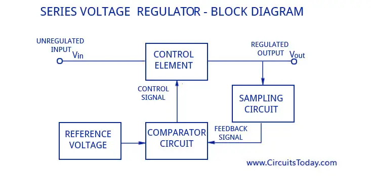
The series voltage regulator can be defined as a regulator which has the limitations like high dissipation, less efficient, and the transistor voltage and Zener diode voltages are affected once the temperature rises. Circuit Design of Transistor Series Voltage Regulator This voltage regulator circuit design is shown below.
