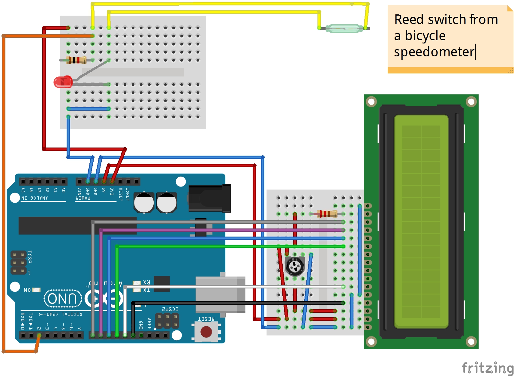
Bicycle speedometer with Arduino Circuit Diagram As previously mentioned, the circuit may be calibrated using the 10K setting at pin #5 of the IC in the way shown below. Begin paddling as fast as you can after putting your bike on stand. At the same time, change the preset such that the tenth LED only starts to light up when the bicycle wheel rotates to its maximum.
Creating a Bike Speedometer: This Instructable explores designing a speedometer to measure and display the speed of a bicycle wheel using a magnetic sensor. The digital circuit on this design converts the frequency detector output bits (from Table 1) to a 3-bit binary sequence, which is output on B2:B0. Step 3: First Design: Extended
Simplest Speedometer Circuit for Your Bicycle using a Voltmeter Circuit Diagram
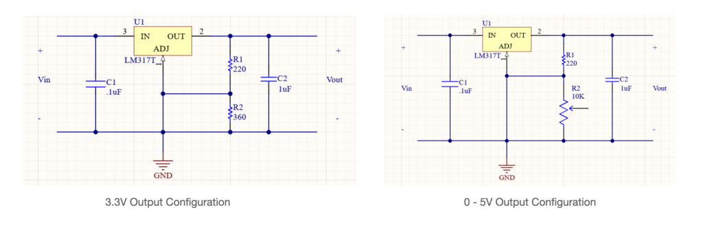
Here we'll see how a simple yet accurate analogue speedometer circuit can be constructed at home using just a single IC and a few external passive components. The speedometer can be universally used with all 2-wheeler, 3-wheeler, even in bicycles for indicating their speeds.

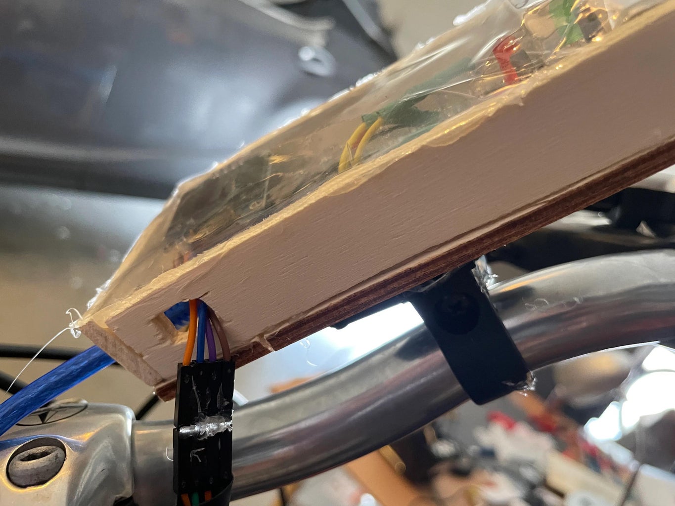
The dimensions of the enclosure are 3.5"x4"x2". I modeled the box in AutoCAD and generated the laser cut files (with finger joints) in Autodesk 123D Make. Then I added two holes for the switches and a rectangular opening for the LCD screen. I also added some holes on the bottom of the enclosure to make attaching it to the bike easier.

DIY Cycle Speedometer : 6 Steps (with Pictures) Circuit Diagram
This project came to my mind when doing my MEM (Mechanical Engineering Measurement) project, a subject in my B.tech. The idea is to measure the angular velocity of my bicycle's wheel. Thus knowing the diameter and the all time mathematical legend the pi(3.14) the speed can be calculated. Also knowing the number of time the wheel has rotated I then take that information and compile it into a language that is super easy to understand. My goal is to make those complex electronics circuit concepts and technical terms much more accessible for all the new and budding electronics engineers out there. I can also design customized circuit diagrams as required by the users.