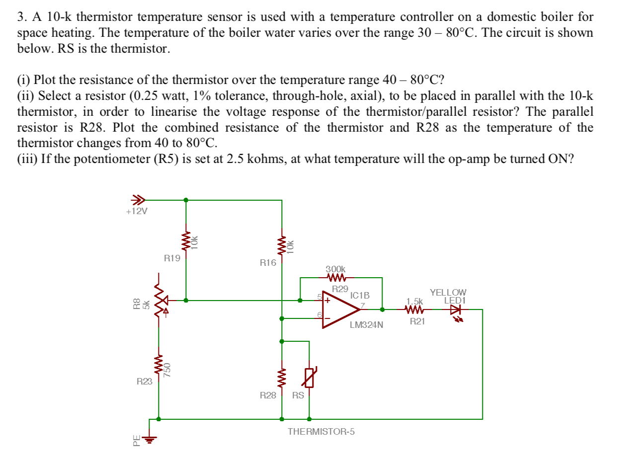
3 A 10k thermistor temperature sensor is used with Circuit Diagram Hello to everyone, a little help please? I want to build a thermistor temp sensor using arduino (as in above circuit) but then need to convert measured temperature in degrees centigrade to air flow in meters per second, and be able to display on screen, and record this via computer. Any help suggestions greatly appreciated. regards Andrew
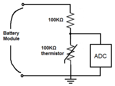
NTC thermistor circuit design. In this section, we will design an NTC circuit that is designed to measure PCB temperatures from 0°C to 100°C. NTC thermistor circuit. The simplest circuit to measure temperature with a thermistor is to use the thermistor as part of a resistor divider circuit, as shown in Figure 1. Figure 1. NTC Thermistor Circuit

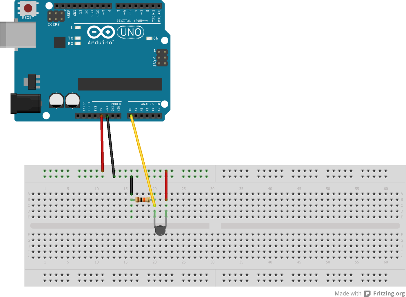
Make an Arduino Temperature Sensor using Thermistor Circuit Diagram
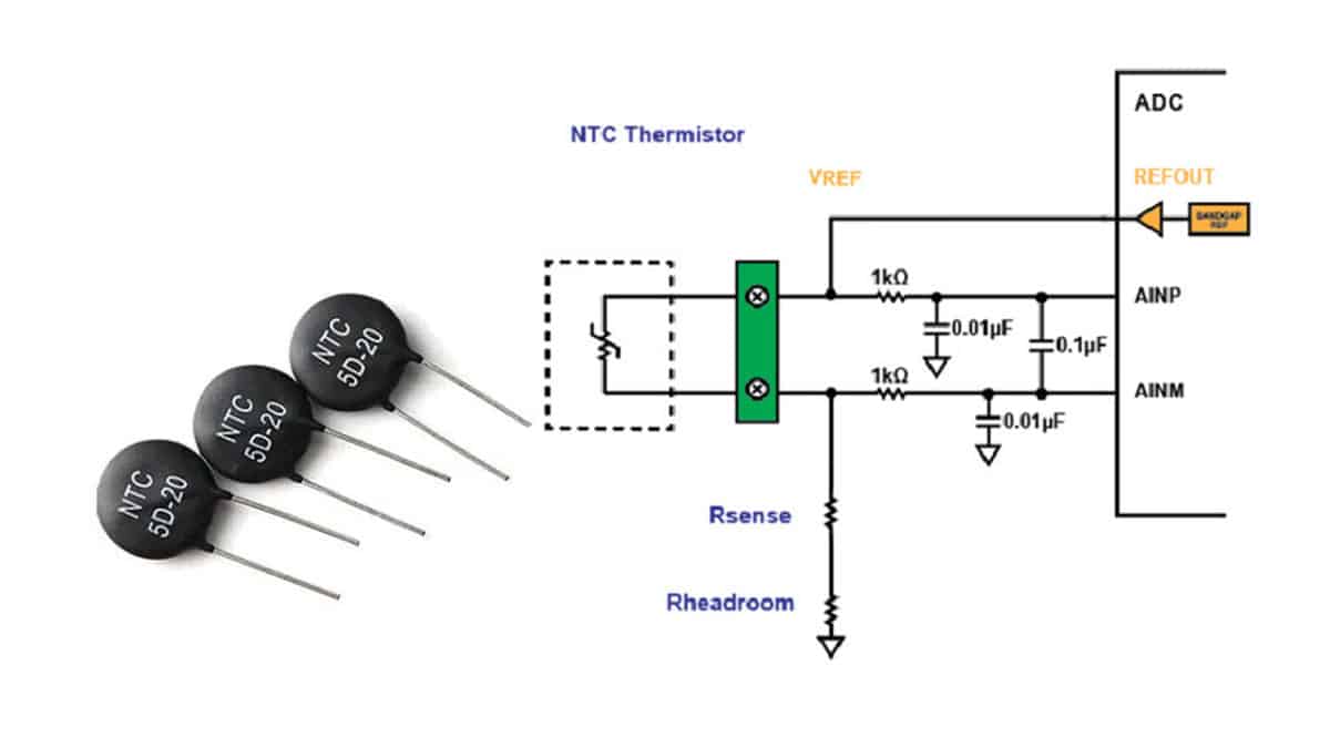
1. For temperature sensing using a PTC thermistor, the resistor, R1, is chosen based on the temperature range and the PTC's value. 2. Operate within the linear output voltage swing (See A OL specification) to minimize non-linearity errors. 3. The reference voltage, Vref, can be created using a DAC or voltage divider. If a voltage
This property of the thermistor helps us to make use of it to sense the temperature of the surroundings. The circuit makes use of two BC547 NPN transistors to switch the alarm when the temperature above desired value is detected. The IC 4011 which is used in the circuit is a quad NAND gate integrated circuit. It has four NAND gates assembled in
How to make temperature sensor circuit using thermistor Circuit Diagram
Figure 3. The current excitation of a thermistor. Another option is to set the gain but use a dynamic excitation current. So, as the signal level from the thermistor changes, the excitation current value is changed dynamically so that the voltage generated across the thermistor is within the electronics' specified input range.
Make an Arduino Temperature Sensor (Thermistor Tutorial) Scott Campbell 132 6 min read. Learn how to use an analog thermistor to measure temperature on the Arduino. Output readings to an LCD or the serial monitor in Celsius or Fahrenheit. PIR sensors can be used to trigger alarms, activate video cameras, or turn on lights when a person or The thermistor is basically a thermal resistor. That means its resistance changes according to the change in temperature of the environment. We can use a thermistor to measure the temperature of the environment. If you want simple, inexpensive, and accurate components to get the temperature data for your project thermistor would be a good choice.

PDF Temperature Sensing with Thermistors (Rev. A) Circuit Diagram
This circuit is very sensitive to heat since we connected two transistors as a Darlington pair. Other than that we have used an LED along with a current limiting resistor, a variable resistor, and a thermistor. Thermistors are used to limit the passage of current through them according to the temperature.